

Clock Recovery in GNU AIS
This is my first post on this subject. I’ve been studying the AIS as a hobby for some time now. My goal was to study the current state of SDR decoders and see if I could improve them in any way. My plan is first to sort out my notes and second to document and share all my findings, in the hope this might be useful for somebody, including a future me.
From my previous experience with P25, I learned how critical symbol synchronization is in the decoding of digital signals. Being a 4-level signal, the P25 is a beast on its on. The 2-level GMSK modulation of AIS makes its analysis much easier to understand and for me to explain.
The most popular AIS software decoder implementation, at the time I write this, is the excellent GNU AIS project, by Ruben Undheim and Heikki Hannikainen. Let’s take a look at how they synchronize with the incoming signal. From receiver.c:
#define INC 16
rx->pll = 0;
rx->pllinc = 0x10000 / 5;

//...

for (i = 0; i < len; i++) {
    out = filtered[i];
    curr = (out > 0);
    if ((curr ^ rx->prev) == 1) {
        if (rx->pll < (0x10000 / 2)) {
            rx->pll += rx->pllinc / INC;
        } else {
            rx->pll -= rx->pllinc / INC;
        }
    }
    rx->prev = curr;
    rx->pll += rx->pllinc;
    if (rx->pll > 0xffff) {
        /* slice */
        bit = (out > 0);
        /* nrzi decode */
        b = !(bit ^ rx->lastbit);
        /* feed to the decoder */
        protodec_decode(&b, 1, rx->decoder);
        rx->lastbit = bit;
        rx->pll &= 0xffff;
    }
}
The code is not so well documented but its concise and its intentions are clear. As important context information note that this code is expecting to receive a signal sampled at 48kHz. Since the AIS symbol rate is 9600bps, then we have exactly 5 samples per symbol (SPS). Note also that the AIS uses a NRZI encoding: a zero-crossing during a symbol period indicates a “zero,” no zero-crossing is indicative of a “one.”
We see how
if ((curr ^ rx->prev) == 1) {detects a crossing by zero (the authors are assuming that the signal is without any DC offsets). If the crossing occurs earlier than 1/2 of the symbol period (early), the running period (in the rx->pll variable) is adjusted increasing it by 1/16 of the sampling period, otherwise (late) the running period is decreased by the same amount. So this is a simple but effective closed-loop clock recovery by adjusting itself with the zero crossings.
Let’s take a closer look at how it performs. Actually it does quite well most of the time. To be honest I had to spent some time finding an example that challenged this algorithm, such as this one:

A closer analysis reveals that the GNU AIS decoder makes one mistake early on, specifically 7 symbols right after the training sequence. Let’s take a closer look:
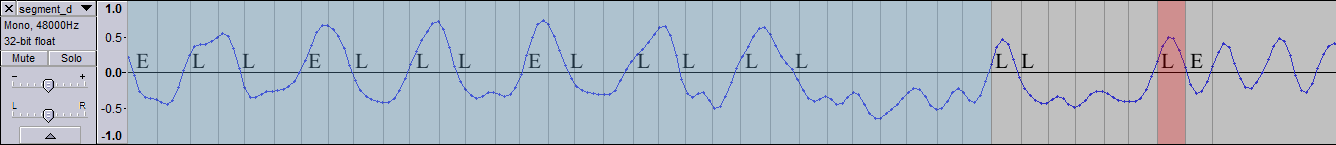
I have highlighted with a blue shade the training sequence and with vertical lines the segments that the clock recovery algorithm considers as symbol boundaries. Remember that this algorithm will try to keep the zero-crossings in the middle of the symbol period and then notice how in this particular case it’s not working so well. Most of the zero-crossings are dangerously close to the symbol boundaries. The “E” indicates that the algorithm considers the crossing as early, likewise the “L” stands for late. I won’t get into a lot of detail but just say that the algorithm is misjudging the crossings marked as early in this example. It seems like if you are late enough, you start to look more as early. Additionally, the 1/16 correction factor is working too slowing. As a result, at the symbol period highlighted in red, the poor timing produces a mistake in the bit value. No zero-crossing is detected during this period, where the opposite is true. With the correct timing we should have detected two zero-crossings in the two consecutive periods.
The eye diagram for this signal presents an overall picture
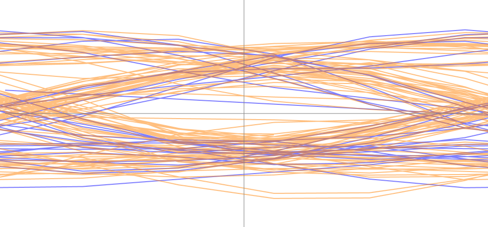
The initial training sequence is colored in purple and the rest of the signal in orange. Notice how the central “eye” is not as wide and clear as it could be in ideal conditions -hence the challenge- but it’s also true that there are not spurious zero-crossings inside the eye. There is a wide gap between zero-crossings at the left and right clusters, therefore with proper timing it is apparent that we should be able to recover the digital signal without errors. Notice also how the timing at the training sequence doesn’t stand out as significantly different from that of the rest of the signal. It seems then that it might be possible to decode the signal with timing information extracted just from the training sequence.
These are some of the limitations of the clock recovery algorithm that I’ve found so far:
- No accounting for signals affected by a DC offset.
- Slow correction factor.
- Misjudgements in the early/late crossing assessment.
On the positive side I have to say that the code does an excellent job in most cases and its conceptual simplicity and straightforward implementation. This can be a key feature when the code runs on a limited embedded processor, although that’s not the case of GNU AIS which is targeting a computer running a full OS such as Linux.
I’m concluding this article now. Next I’ll cover the M&M clock recovery algorithm that is used by another popular AIS SDR decoder. After that I’ll propose an alternative approach.
Leave a Comment